MECHANICAL SERVICES
Fabrication of Steel Structure
Structural steel fabrication can be carried out in shop or at the construction site. Fabrication of steelwork carried out in shops is precise and of assured quality, whereas field fabrication is comparatively of inferior in quality.
In construction site fabrication is most common even in large projects due to inexpensive field labor, high cost of transportation, difficulty in the transportation of large members, higher excise duty on products from shop. Beneficial taxation for site work is a major financial incentive for site fabrication.
 The methods followed in site fabrication are similar but the level of sophistication of equipment at site and environmental control would be usually less. The skill of personnel at site also tends to be inferior and hence the quality of finished product tends to be relatively inferior. However, shop fabrication is efficient in terms of cost, time and quality.
-
Structural steel passes through various operations during the course of its fabrication. Generally, the sequence of activities in fabricating shops is as shown in Table1.
The sequence and importance of shop operations will vary depending on the type of fabrication required. All these activities are explained briefly in the subsequent parts of the section

Fabrication of Mechanical Storage Tanks
 o Atmospheric:
An atmospheric tank is a container for holding a liquid at atmospheric pressure. The major design code for welded atmospheric tanks are API 650 and API 620. API 653 is used for analysis of in-service storage tanks. In Europe the design code is Euro code 3 (EN 1993), part 4-2.
o High pressure
Horizontal, cylindrical shell, elliptical heads carbon steel pressure vessel
In the case of a liquefied gas such as hydrogen or chlorine, or a compressed gas such as compressed natural gas or MAPP, the storage tank must be made to withstand the sometimes immense pressures exerted by the contents. These tanks may be called cylinders and, being pressure vessels, are sometimes excluded from the class of "tanks".
-
o Thermal storage tanks
One form of seasonal thermal energy storage (STES) is the use of large surface water tanks that are insulated and then covered with earth berms to enable the year-round of solar-thermal heat that is collected primarily in the summer for all-year heating.
 A related technology has become widespread in Danish district heating systems. The thermal storage medium is gravel and water in large, shallow, lined pits that are covered with insulation, soil and grass.
Ice and slush tanks are used for short-term of cold for use in air conditioning, allowing refrigeration equipment to be run at night when electric power is less expensive, yet provide cooling during hot daytime hours.
-
o Milk tank
In dairy farming a bulk milk cooling tank is a large storage tank for cooling and holding milk at a cold temperature until it can be picked up by a milk hauler. The bulk milk cooling tank is an important milk farm equipment.
It is usually made of stainless steel and used every day to store the raw milk on the farm in good condition. It must be cleaned after each milk collection. The milk cooling tank can be the property of the farmer or being rented to the farmer by the dairy plant.
o Septic tank
A septic tank is part of a small scale sewage treatment system often referred to as a septic system; it consists of the tank and a septic drain field. Waste water enters the tank where solids can settle and scum floats. Anaerobic digestion occurs on the settled solids, reducing the volume of solids. The water released by the system is normally absorbed by the drain field without needing any further treatment.
 o Mobile "storage" tanks
While not strictly a "storage" tank, mobile tanks share many of the same features of storage tanks. Also, they must be designed to deal with a heavy sloshing load and the risk of collision or other accident. Some of these include ocean-going oil tankers and LNG carriers; railroad tank cars; and the road and highway traveling tankers. Also included are the holding tanks which are the tanks that store toilet waste on RVs and boats.
Fabrication of Steel Frames
Cutting is done by sawing, shearing, or chiseling (all with manual and powered variants); torching with hand-held torches (such as oxy-fuel torches or plasma torches); and via numerical control (CNC) cutters (using a laser, mill bits, torch, or water jet).
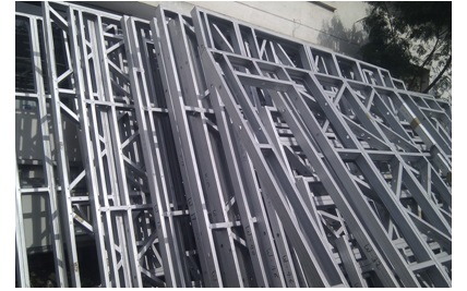 Bending is done by hammering (manual or powered) or via press brakes and similar tools. Modern metal fabricators use press brakes to either coin or air-bend metal sheet into form. CNC-controlled back gauges use hard stops to position cut parts in order to place bend lines in the correct position. Off-line programing software now makes programing the CNC-controlled press brakes seamless and very efficient.
Assembling (joining of the pieces) is done by welding, binding with adhesives, riveting, threaded fasteners, or even yet more bending in the form of a crimped seam. Structural steel and sheet metal are the usual starting materials for fabrication, along with the welding wire, flux, and fasteners that will join the cut pieces. As with other manufacturing processes, both human labor and automation are commonly used.
The product resulting from fabrication may be called a fabrication. Shops that specialize in this type of metal work are called fab shops. The end products of other common types of metalworking, such as machining, metal stamping, forging, and casting, may be similar in shape and function, but those processes are not classified as fabrication.
Installation of HVAC System
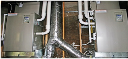
The three central functions of heating, ventilation, and air conditioning are interrelated, especially with the need to provide thermal comfort and acceptable indoor air quality within reasonable installation, operation, and maintenance costs. HVAC systems can be used in both domestic and commercial environments.
HVAC systems can provide ventilation, reduce air infiltration, and maintain pressure relationships between spaces. The means of air delivery and removal from spaces is known as room air distribution.
 o Individual systems
In modern buildings the design, installation, and control systems of these functions are integrated into one or more HVAC systems. For very small buildings, contractors normally estimate the capacity, engineer and select HVAC systems and equipment. For larger buildings, building service designers, mechanical engineers, or building services engineers analyze, design, and specify the HVAC systems.
Specialty mechanical contractors then fabricate and commission the systems. Building permits and code-compliance inspections of the installations are normally required for all sizes of building.
-
o District networks Although HVAC is executed in individual buildings or other enclosed spaces the equipment involved is in some cases an extension of a larger district heating (DH) or district cooling (DC) network, or a combined DHC network. In such cases, the operating and maintenance aspects are simplified and metering becomes necessary to bill for the energy that is consumed, and in some cases energy that is returned to the larger system. For example, at a given time one building may be utilizing chilled water for air conditioning and the warm water it returns may be used in another building for heating, or for the overall heating-portion of the DHC network (likely with energy added to boost the temperature). Basing HVAC on a larger network helps provide an economy of scale that is often not possible for individual buildings, for utilizing renewable energy sources such as solar heat, winter's cold, the cooling potential in some places of lakes or seawater for free cooling, and the enabling function of seasonal thermal energy storage.
Installation of Sanitary Sewers
Sewage treatment is less effective when sanitary waste is diluted with storm water, and combined sewer overflows occur when runoff from heavy rainfall or snowmelt exceeds hydraulic capacity of sewage treatment plants.
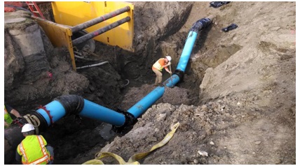 To overcome these disadvantages, some cities built separate sanitary sewers to collect only municipal wastewater and exclude storm water runoff collected in separate storm drains.
The decision between a combined sewer system and two separate systems is mainly based on need for sewage treatment and cost of providing treatment during heavy rain events. Many cities with combined sewer systems built prior to sewage treatment have not replaced those sewer systems.
Installation of Storm Water Sewer
There are two main types of storm water drain (highway drain or road gully inlets: side inlets and grated inlets. Side inlets are located adjacent to the curb (kern) and rely on the ability of the opening under the back stone or lintel to capture flow. They are usually depressed at the invert of the channel to improve capture capacity. Many inlets have gratings or grids to prevent people, vehicles, large objects or debris from falling into the storm drain. Grate bars are spaced so that the flow of water is not impeded, but sediment and many small objects can also fall through. However, if grate bars are too far apart, the openings may present a risk to pedestrians, bicyclists, and others in the vicinity. Grates with long narrow slots parallel to traffic flow are of particular concern to cyclists, as the front tire of a bicycle may become stuck, causing the cyclist to go over the handlebars or lose control and fall. Storm drains in streets and parking areas must be strong enough to support the weight of vehicles, and are often made of cast iron or reinforced concrete. Some of the heavier sediment and small objects may settle in a catch basin, or sump, which lies immediately below the outlet, where water from the top of the catch basin reservoir overflows into the sewer proper. The catch basin serves much the same function as the "trap" in household wastewater plumbing in trapping objects.
-
Unlike the plumbing trap, the catch basin does not necessarily prevent sewer gases such as hydrogen sulfide and methane from escaping. However, where they are called gully pots, they are designed as true water-filled traps and do block the egress of gases and rodents.
Most catch basins will contain stagnant water during the drier parts of the year, and can, in warm countries, be used by mosquitos for breeding.
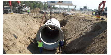 The performance of catch basins at removing sediment and other pollutants depends on the design of the catch basin (for example, the size of the sump), and on routine maintenance to retain the storage available in the sump to capture sediment. Municipalities typically have large vacuum trucks that perform this task.
Catch basins act as a first-line pretreatment for other treatment practices, such as retention basins, by capturing large sediments and street litter from urban runoff before it enters the storm drainage pipes.
Installation of oily water Sewer
All waste water effluents from the industries which are discharged to public and/or natural water sources or directed to recycling purpose inside the industry and may contain a wide variety of matters in solution or suspension should be controlled according to the requirements imposed by the final destination.
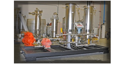 However, in any case elimination of the waste or the hazard potential of the waste shall be ultimate goal in the management of hazardous wastes. Under no circumstances shall the effluent water cause oil traces on the surface or embankments of the receiving water, or affect the natural self-purification capacity of the receiving water to such an extent that it would cause hindrance to others. Under no conditions shall polluted streams be combined with unpolluted streams if the resultant stream would then require purification.
Installation of Valve Package
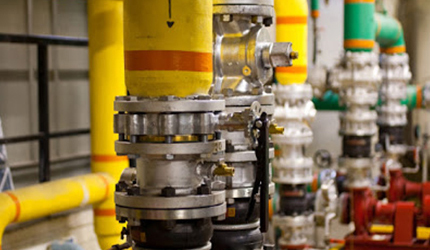
Standard valve packages available as a factory built assembly and field-installed option for the main cooling coil and optional heating coil. Vertical Hi-Stack Fan Coils are the exception where all valve packages are factory installed. All valve packages are manufactured within strict tolerances and are hydrostatically tested for leaks. Valve packages are shipped loose for field assembly to ensure a leak free system as factory mounted valve packages often become damaged during shipment. All cooling piping and components are located directly above the auxiliary drain pan to allow condensate to be captured and properly drained. Insulation of the factory valve package is not required. However, all field connections downstream of the valve package should be insulated to prevent condensation from missing the auxiliary drain pan. Valve package components valve packages consist of a variety of components and selection of each combination is dependent upon the application. The following sections provide a detailed description of each of the components. Following this section are additional schematic illustrations and mechanical specifications and photos. Piping system/placement Valve packages are available for two or four-pipe systems with left and/or right hand connections. The heating and cooling connections can be located on the same or opposite sides of the unit in four-pipe systems. All coil connections are left hand as standard unless specified differently. Interconnecting piping interconnecting piping refers to the copper piping which is attached to the coil connections and to which all other components (i.e. control valves, end valves, circuit setters, etc.) are attached. Piping is ½" nominal (5/8" OD) copper. Deluxe or basic valve packages the basic valve package includes only the main components of the valve package (i.e., interconnecting piping, control valves, and end valves). The deluxe valve packages also include unions at the coil connections and a strainer on the supply water pipe along with the basic components. All valve package components are solder end connections. Unions The unions are cast bronze construction and close with a minimum amount of effort. Used for quick connect and disconnect of valve package components to minimize required field labor during servicing of the unit. Strainer the Y-type strainer body is constructed of brass with a 16 mesh 304 stainless steel screen. Used for removal of small particles from the water supply pipe during normal system operation. The strainer helps protect the coil and minimizes the chance of control valves clogging. Screens should be regularly removed and cleaned as part of a routine maintenance schedule.
-
Balance valves the balance valve body is constructed of bronze and is used to balance hydronic circuits.
End valves Each basic and deluxe valve package includes a ball valve for the supply water pipe and one of the following end valves on the return water pipe; ball valve, manual circuit setter, or automatic circuit setter. These valves serve as the field connection points on all of the Rattling valve packages. Consult the factory for inclusion of the other types of valves as end valves.
Ball valves Ball valves, also known as end valves, allow the unit to be cut off for servicing purposes. They have a low resistance to water flow, operate easily, and are often used for water balancing. These valves have a compact handle that rotates 90 degrees to a fully open position. The valve body is forged brass and the ball is polished brass with virgin Teflon seats and seals. Ball valves are available as end valves on both the supply and return water pipes.
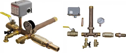 Manual circuit setter A manual circuit setter, also known as a manual flow control valve, acts as both a flow setting device and a stop valve, taking the place of a ball valve. This valve allows water flow through the fan coil unit and can be set quickly and accurately. The manual circuit setter includes two measuring ports in the valve body to be used for pressure drop measurements during system balancing. This pressure drop can be compared to factory-supplied curves showing the corresponding flow rate. This valve shall have a 360-degree turn hand wheel with memory feature including a locking feature for tamperproof setting.
Automatic circuit setter an automatic circuit setter is an automatic flow control device that includes a ball valve cast in the valve body and is located on the return water pipe. The automatic circuit setter consists of a stainless steel/brass flow cartridge and a contoured orifice plate. As the pressure drop increases, the flow cartridge will move into the contoured orifice plate to decrease the flow. This flexing action provides a constant flow, independent of pressure (2-80 psi), and makes it difficult to clog and resistant to cavitation damage. This valve sets flow through the coil without any action required by a system balancer. The automatic circuit setter includes two measuring ports in the valve body to be used for pressure drop and temperature measurements.
Control valves Valve packages are available with or without control valves. All control valve packages are shipped loose for field mounting and wiring.
-
2-way on/off valves these 1/2" valves are normally closed to the coil as standard and will isolate the coil during a loss of power. Normally open valves are also available upon request. Upon response to a signal from the controller, the valve will be either fully open or fully closed. These valves are located in the water supply pipe, have a CV of 3.5, and close off DP of 20 psi. A means of relieving pump head pressure must be accounted for when two-way valves are selected, most notably when used in combination with automatic changeover. 3-way on/off valves these 1/2" valves are normally closed to the coil as standard and will isolate the coil during a loss of power. Normally open configurations are simply achieved by turning the valve around. Upon response to a signal from the controller, the valve will be either fully open allowing full flow to the coil or fully closed to the coil diverting full flow to the bypass line. All 3-way valve configurations include a balance fitting in the bypass line to allow proper flow balancing. These valves are located in the water supply pipe, have a CV of 4.0, and close off DP of 20 psi. 2-way modulating valves these 1/2", 24V valves modulate the flow of water (0-100%) through the coil in response to a signal from the controller and are normally closed to the coil as standard. Normally open valves are also available upon request. All modulating valves are three-wire floating equal percentage valves, designed for precise temperature control. All valves feature a magnetic clutch to extend the life of the motor and gear train, manual operating lever/position indicator facilitates field setup, and easy to use lever terminal blocks. These valves are located in the water supply pipe, have a CV of 4.0, and close off DP of 50 psi. A means of relieving pump head pressure must be accounted for when two-way valves are selected, most notably when used in combination with automatic changeover. 3-way modulating valves these 1/2", 24V valves modulate the flow of water (0-100%) through the coil in response to a signal from the controller and are normally closed to the coil as standard. Normally open configurations are simply achieved by turning the valve around. 3-way valves allow the water supply from the water supply pipe to mix with bypass water from the bypass line. This mixture exits through the supply water pipe to the coil. Modulating three-wire floating type valves are compatible with any 24V three-wire signal when three-minute time-out logic resides in the system controller. Modulating proportional type valves are compatible with any 0 to 10 VDC or 4 to 20 mA signal with jumper selectable operating range and action resulting in precise positioning. All valves feature a magnetic clutch to extend the life of the motor and gear train, manual operating lever/position indicator facilitates field setup, and easy to use lever terminal blocks. These valves are located in the water supply pipe, have a CV of 4.0, and close off DP of 50 psi.
Installation of Pipe Spool
The installation of pipe systems follows its fabrication and is very frequently a part of it. The installation of pipe can be accomplished in the following two primary ways, or combinations thereof:
A) Field fabricate and install
B) Shop fabricate and field erected
Some contractors prefer to do most, if not all fabrication in the shop, others prefer to set up at the job-site, while others are flexible enough to utilize the best of both methods.
Field fabrication and installation is exactly what it means. The pipe is fabricated on-site, either directly at the place where it is mounted, or in a temporary accommodation in the field.
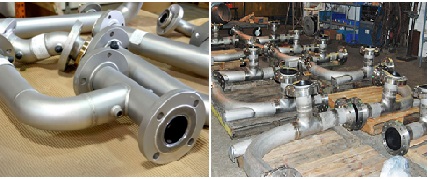 A number of factors will determine whether it is profitable to fabricate pipe on site:
Type of project, size and scope of the project, pipe size and material, accessibility of the equipment, surface treatment after fabrication, weather conditions, availability of qualified personnel, time available to do the job, etc.
Installation of Monorail Crane
Be familiar with all hanger types used for suspension – see the O&M manual section titled “Suspension.”
Each hanger is designed to handle the listed maximum capacity and is utilized in the system to the designated maximum hanger load.
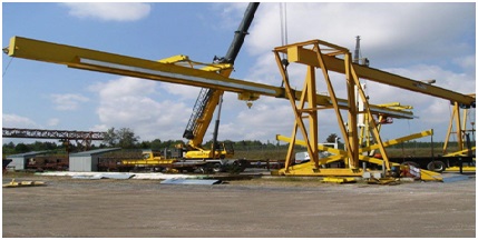 Be certain that each hanger is used at its designated point. Some systems use more than one hanger variety.
There are four types of suspension methods: rigid stools, flexible rod, direct bolt, and direct bolt to brackets.
High-strength rods are used on all flexible rod suspension systems. Do not, under any circumstances, weld or apply heat to any load carrying rod.
All load carrying fasteners are minimum grade 5 or A325 grade. Any fasteners of a lesser grade will change the hanger or clamp capacity.
A flat washer must be used if the diameter of the hole is greater than 1/16" above the fastener diameter or has a slotted hole. Each fastener must have a lock washer under its nut.
Shimming at hanger points may be necessary to assure that the rail is installed level.
After final leveling, at all hanger rod suspension points check that spherical washers are seated properly. Tighten the set screw on each lock nut, then insert the spring pins.
Be certain that all hanger rods are plumb.
Recheck fasteners to be certain that all are secured and washers are properly placed.
Installation of Cantilever Crane
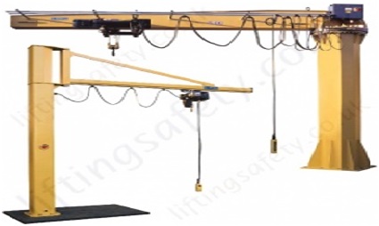 Read entire manual before installing the crane. Check packing list to ensure no parts have been lost prior to initiating assembly of crane. Tools and materials (by others) typically needed to assemble crane:
• Torque wrench
• Ladders/man lifts
• Hand tools
• Leveling tools (plumb bob, plumb fixture-)
• Allen wrenches Lifting device to lift heavy masts and booms
• Steel shims
• Grout (Non-Shrink Precision Grout)
• Base Plate Template
• Anchor Bolts (by others, grade 5 or better) Identify crane type.
Installation of Gantry Crane
For assembly, when possible, select an area under an overhead hoist, or where a lift truck can be used to raise the I-beam. Be sure there is no machinery or clutter nearby that will hamper free movement. All personnel should be wearing applicable safety gear such as hard hats and safety shoes.
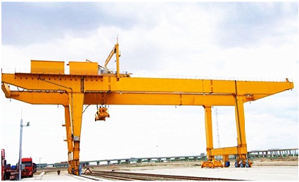 Lay both “A” frames flat on the floor. Using an overhead hoist or truck lift, lift the I-beam to the gantry’s minimum height (On adjustable height models uprights are secured in a frames at minimum height before shipment from factory). Be sure that the holes in the I-beam flange are on the bottom on fixed height and span models that the capacity rating is right side up and legible.
Lift one end frame assembly into position under one end of the I-beam, and bolt the I-beam to the top plate of the upright with the hardware supplied.
We certify that the equipment referenced in this manual is in conformance with our interpretation of applicable CMAA 74, ANSI B30.17, AISC ASD 9th Edition, and AWS D1.2-90. This equipment is designed and manufactured to the rated capacity marked on the equipment with due allowances for safety factors. It is recommended that a person appointed by the owner, under the direction of a qualified technical person, shall perform a load test of 125% of the rated capacity before placing the unit into service. See the latest edition of ANSI B30.17 for clarification of details related to rated load tests.
Your gantry is now ready to use, and if it is an adjustable model, you can now adjust the I-beam to your desired height.
Installation of Magnetic Crane
Installation of Magnetic Crane is done on Gantry Monorail or Cantilever Standard type crane, as a third component depending on the client condition we have to install this as a requirement.
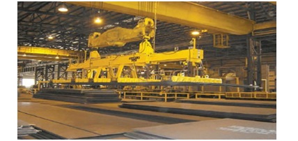 Depending on the Load and Scenario of working condition.
Installation of Degasser
The Vacuum Degasser is an online degasser system with high efficiency. Dissolved gasses are removed from the solvents by applying vacuum to a semi-permeable membrane.
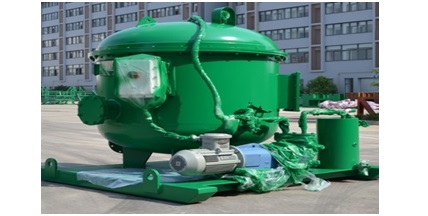 The Vacuum Degasser is available as 1-Channel, 2-Channel, 3-Channel, or 4-Channel version. Each solvent channel can used for a different solvent or several channels can be used in series to increase the efficiency even more.
The vacuum pump is operated at a constant speed. The Vacuum Degasser vacuum level is not regulated in any way. The maximum vacuum level reached is the physical maximum possible with the system setup, consisting of vacuum chamber(s) and vacuum pump.
Installation of Mechanical Equipment
The Contractor shall provide supervision, labor, equipment, materials, tools, and supplies unless specifically noted as being provided by others, to perform the work described herein in accordance with this document and the referenced specification, drawings, and related documents. Work not specifically shown on the drawings or enumerated herein but that is reasonably necessary for the proper completion of the contract shall be provided by the Contractor the same as if shown on the drawings or enumerated herein.
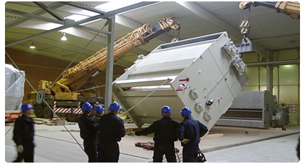 The mechanical equipment shall be installed in accordance with all applicable federal, state and local codes, standards, rules, regulations, and laws including, but not limited to, the codes and standards referenced in the Specification.
Unload OWNER furnished equipment and materials. Load and transport equipment and materials from the storage area to the installation location.
Install all the equipment shown on the drawings or as noted in other contract documents.
Equipment installation shall include the supply and placement of grout for equipment or materials and the supply and installation of anchors and fasteners as required for a complete installation.
Motor driven equipment placement shall include alignment, assembly of belts, sheaves, couplings, guards, etc. as required for a complete installation.
The Contractor shall inspect the location for the equipment to be installed prior to beginning installation to insure readiness of area including anchor bolt locations, size, projections and placement of support steel where applicable.
Work in an area shall be coordinated through the OWNER Construction Manager. No installation of equipment shall be installed without release of the area for such installation.
All materials and equipment furnished by the Contractor shall be in accordance with the specifications. Substitution of any materials deviating from the specifications and drawings shall be approved in writing by OWNER. A description of Contractor supplied substituted material shall be submitted to the OWNER Construction Manager for approval.
TIG-Welding
Gas tungsten arc welding (GTAW), also known as tungsten inert gas (TIG) welding, is an arc welding process that uses a non-consumable tungstenelectrode to produce the weld. The weld area is protected from atmospheric contamination by an inertshielding gas (argon or helium), and a filler metal is normally used, though some welds, known as autogenous welds, do not require it. A constant-currentwelding power supply produces electrical energy, which is conducted across the arc through a column of highly ionized gas and metal vapors known as a plasma.
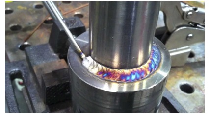 GTAW is most commonly used to weld thin sections of stainless steel and non-ferrous metals such as aluminum, magnesium, and copper alloys. The process grants the operator greater control over the weld than competing processes such as shielded metal arc welding and gas metal arc welding, allowing for stronger, higher quality welds. However, GTAW is comparatively more complex and difficult to master, and furthermore, it is significantly slower than most other welding techniques. A related process, plasma arc welding, uses a slightly different welding torch to create a more focused welding arc and as a result is often automated.
MIG/MAG Welding
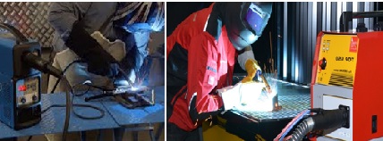
Gas metal arc welding (GMAW), sometimes referred to by its subtypes metal inert gas (MIG) welding or metal active gas (MAG) welding, is a welding process in which an electric arc forms between a consumable wireelectrode and the work piece metal(s), which heats the work piece metal(s), causing them to melt and join.
Along with the wire electrode, a shielding gas feeds through the welding gun, which shields the process from contaminants in the air. The process can be semi-automatic or automatic. A constant voltage, direct current power source is most commonly used with GMAW, but constant current systems, as well as alternating current, can be used. There are four primary methods of metal transfer in GMAW, called globular, short-circuiting, spray, and pulsed-spray, each of whichhas distinct properties and corresponding advantages and limitations
 Originally developed for welding aluminium and other non-ferrous materials in the 1940s, GMAW was soon applied to steels because it provided faster welding time compared to other welding processes. The cost of inert gas limited its use in steels until several years later, when the use of semi-inert gases such as carbon dioxide became common. Further developments during the 1950s and 1960s gave the process more versatility and as a result, it became a highly used industrial process. Today, GMAW is the most common industrial welding process, preferred for its versatility, speed and the relative ease of adapting the process to robotic automation. Unlike welding processes that do not employ a shielding gas, such as shielded metal arc welding, it is rarely used outdoors or in other areas of air volatility. A related process, flux cored arc welding, often does not use a shielding gas, but instead employs an electrode wire that is hollow and filled with flux.
SMAW Welding
Shielded metal arc welding (SMAW), also known as manual metal arc welding (MMA or MMAW), flux shielded arc welding or informally as stick welding, is a manual arc welding process that uses a consumable electrode covered with a flux to lay the weld.
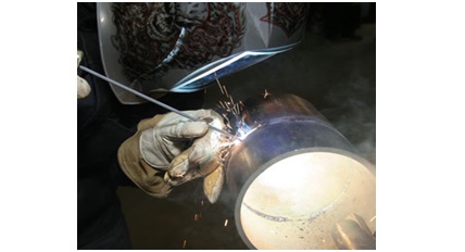 An electric current, in the form of either alternating current or direct current from a welding power supply, is used to form an electric arc between the electrode and the metals to be joined. The work piece and the electrode melts forming a pool of molten metal (weld pool) that cools to form a joint. As the weld is laid, the flux coating of the electrode disintegrates, giving off vapors that serve as a shielding gas and providing a layer of slag, both of which protect the weld area from atmospheric contamination.
Because of the versatility of the process and the simplicity of its equipment and operation, shielded metal arc welding is one of the world's first and most popular welding processes. It dominates other welding processes in the maintenance and repair industry, and though flux-cored arc welding is growing in popularity, SMAW continues to be used extensively in the construction of heavy steel structures and in industrial fabrication. The process is used primarily to weld iron and steels (including stainless steel) but aluminium, nickel and copperalloys can also be welded with this method.
Spot Welding
Resistance spot welding (RSW) is a process in which contacting metal surfaces are joined by the heat obtained from resistance to electric current.
Work-pieces are held together under pressure exerted by electrodes. Typically the sheets are in the 0.5 to 3 mm (0.020 to 0.118 in) thickness range. The process uses two shaped copper alloyelectrodes to concentrate welding current into a small "spot" and to simultaneously clamp the sheets together. Forcing a large current through the spot will melt the metal and form the weld. The attractive feature of spot welding is that a lot of energy can be delivered to the spot in a very short time (approximately 10–100 milliseconds). That permits the welding to occur without excessive heating of the remainder of the sheet.
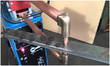 The amount of heat (energy) delivered to the spot is determined by the resistance between the electrodes and the magnitude and duration of the current. The amount of energy is chosen to match the sheet's material properties, its thickness, and type of electrodes. Applying too little energy will not melt the metal or will make a poor weld. Applying too much energy will melt too much metal, eject molten material, and make a hole rather than a weld. Another feature of spot welding is that the energy delivered to the spot can be controlled to produce reliable welds.
Arc Welding
In arc welding, the intense heat needed to melt metal is produced by an electric arc. The arc is formed between the actual work and an electrode (stick or wire) that is manually or mechanically guided along the joint. The electrode can either be a rod with the purpose of simply carrying the current between the tip and the work. Or, it may be a specially prepared rod or wire that not only conducts the current but also melts and supplies filler metal to the joint. Most welding in the manufacture of steel products uses the second type of electrode.
o Basic Welding Circuit
The basic arc-welding circuit is illustrated in Fig. 1. An AC or DC power source, fitted with whatever controls may be needed, is connected by a work cable to the work piece and by a "hot" cable to an electrode holder of some type, which makes an electrical contact with the welding electrode.
An arc is created across the gap when the energized circuit and the electrode tip touches the work piece and is withdrawn, yet still with in close contact.
The arc produces a temperature of about 6500ºF at the tip. This heat melts both the base metal and the electrode, producing a pool of molten metal sometimes called a "crater." The crater solidifies behind the electrode as it is moved along the joint. The result is a fusion bond.
 o Arc Shielding
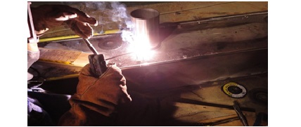
However, joining metals requires more than moving an electrode along a joint. Metals at high temperatures tend to react chemically with elements in the air - oxygen and nitrogen. When metal in the molten pool comes into contact with air, oxides and nitrides form which destroy the strength and toughness of the weld joint. Therefore, many arc-welding processes provide some means of covering the arc and the molten pool with a protective shield of gas, vapor, or slag. This is called arc shielding. This shielding prevents or minimizes contact of the molten metal with air. Shielding also may improve the weld. An example is a granular flux, which actually adds deoxidizers to the weld.
-
o Nature of the Arc
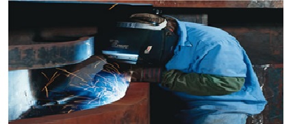
An arc is an electric current flowing between two electrodes through an ionized column of gas. A negatively charged cathode and a positively charged anode create the intense heat of the welding arc. Negative and positive ions are bounced off of each other in the plasma column at an accelerated rate.
In welding, the arc not only provides the heat needed to melt the electrode and the base metal, but under certain conditions must also supply the means to transport the molten metal from the tip of the electrode to the work. Several mechanisms for metal transfer exist. Two (of many) examples include:
Surface Tension Transfer - a drop of molten metal touches the molten metal pool and is drawn into it by surface tension
Spray Arc - the drop is ejected from the molten metal at the electrode tip by an electric pinch propelling it to the molten pool (great for overhead welding)
Our Services
Contact
Office : 013 837 2785
Mobile : 059 943 8600
AL-KHODARYA DAMMAM
KINGDOM OF SAUDI ARABIA
info@habibco-sa.com


